Co-simulating your verilated model
Creating HDL models and co-simulating them in Renode using Verilator is an advanced topic, so be sure to visit the Co-simulating with an HDL simulator chapter beforehand. If you want to use example verilated models as inspiration to build your own ones, visit Antmicro’s GitHub.
Note
You can run this tutorial on Linux and Windows operating systems.
Creating a verilated peripheral
To make your own verilated peripheral, in the main cpp file of your verilated model, you need to include C++ headers applicable to the bus you are connecting to.
You also need to specify the type of external interfaces you want to integrate with Renode - e.g., UART’s rx/tx signals.
// uart.h and axilite.h can be found in Renode's CoSimulationPlugin
#include "src/peripherals/uart.h"
#include "src/buses/axilite.h"
Next, you will need to define a function that will call your model’s eval function and provide it as a callback to the integration library structure, along with bus and peripheral signals.
void eval() {
   top->eval();
   #if VM_TRACE
   main_time++;
   tfp->dump(main_time);
   tfp->flush(); // optional
   #endif
}

void Init() {
AxiLite* bus = new AxiLite();

//==========================================
// Init bus signals
//==========================================
bus->clk = &top->clk;
bus->rst = &top->rst;
bus->awaddr = (unsigned long *)&top->awaddr;
bus->awvalid = &top->awvalid;
bus->awready = &top->awready;
bus->wdata = (unsigned long *)&top->wdata;
bus->wstrb = &top->wstrb;
bus->wvalid = &top->wvalid;
bus->wready = &top->wready;
bus->bresp = &top->bresp;
bus->bvalid = &top->bvalid;
bus->bready = &top->bready;
bus->araddr = (unsigned long *)&top->araddr;
bus->arvalid = &top->arvalid;
bus->arready = &top->arready;
bus->rdata = (unsigned long *)&top->rdata;
bus->rresp = &top->rresp;
bus->rvalid = &top->rvalid;
bus->rready = &top->rready;

//==========================================
// Init eval function
//==========================================
bus->evaluateModel = &eval;

//==========================================
// Init peripheral
//==========================================
uart = new UART(bus, &top->txd, &top->rxd,
   prescaler);
}
As part of the last step, in the main function, you have to call simulate with two port numbers on which Renode awaits communication.
These port numbers are passed as command-line arguments when Renode starts the verilated peripheral.
Init();
uart->simulate(atoi(argv[1]), atoi(argv[2]));
Building a verilated peripheral
There are a few prerequisites:
a local copy of the renode-verilator-integration repository,
a local copy of the Renode repository because of its IntegrationLibrary,
Verilator >= v4.024.
$RVI_PATH, $RENODE_PATH, and $VERILATOR_PATH, respectively, will be used to refer to the paths of these three prerequisites.
The path to Verilator won’t be needed if it’s properly installed, i.e., the executable is available in PATH and the verilator-config.cmake can be found according to the CMake’s find_package search procedure.
The path to the directory containing Verilog and C/C++ source files will be referred to as $SRC_PATH.
It’s best to place that directory directly in the renode-verilator-integration repository root which ensures that the default path to the configure-and-verilate.cmake file that contains the CMake logic common to all peripherals is correct.
Note
To run shell commands without any modifications, set all *_PATH shell variables before running the commands.
Preparing the peripheral directory
First, put all Verilog and C/C++ source files in $SRC_PATH.
Then, copy the $RVI_PATH/cmake/CMakeLists.txt.template as CMakeLists.txt to the $SRC_PATH directory:
# Execute from a directory containing peripheral's source files
mkdir "$SRC_PATH"
cp *.v *.c *.cpp "$SRC_PATH"
cp "$RVI_PATH/cmake/CMakeLists.txt.template" "$SRC_PATH/CMakeLists.txt"
The project’s $SRC_PATH/CMakeLists.txt file needs minor adjustments to work well with a specific peripheral (only the first two are required):
replace
<PROJECT_NAME>with a chosen name,replace
<MODULE_FILES>and<C_SRC_FILES>with paths to the peripheral files relative to the$SRC_PATH,add chosen arguments to be always used during a certain phase of the build by removing
#and replacing<ARGS>with actual arguments in lines that set theCOMP_ARGS,LINK_ARGSandVERI_ARGSvariables,if the peripheral’s source directory isn’t placed directly in
<RVI_PATH>, then adjust the path toconfigure-and-verilate.cmakein theincludecommand.
Note
Use a space to separate multiple files or arguments replacing <*_FILES> and <ARGS> placeholders.
Build commands
Having the CMake source directory prepared, the verilated peripheral can now be built. When using CMake, it’s best to keep the build files in a separate build directory:
mkdir build && cd build
cmake -DCMAKE_BUILD_TYPE=Release -DUSER_RENODE_DIR="$RENODE_PATH" ${VERILATOR_PATH:+"-DUSER_VERILATOR_DIR=$VERILATOR_PATH"} "$SRC_PATH"
make
If the build succeeds, libVtop is the built verilated peripheral.
Note
RENODE_ROOT and VERILATOR_ROOT environment variables can be used instead of CMake USER_RENODE_DIR and USER_VERILATOR_DIR variables (respectively).
In case both environment and CMake variables are specified for Renode or Verilator, CMake variables have higher priority.
Note
Use make -j $(nproc) (make -j $(sysctl -n hw.logicalcpu) on macOS) to optimize build speed by creating as many jobs as the number of available CPU cores.
Linux-specific build information
On Linux, it is advised to use OpenLibm to enable running verilated peripherals with older GNU libc versions. This is because a few common mathematical functions have recently been updated in the GNU libm (a part of GNU libc). If the peripheral is linked against them, you will need these updated functions to run the peripheral.
Pass an additional -DLIBOPENLIBM=$RVI_PATH/lib/libopenlibm-Linux-x86_64.a argument to the cmake command to use the OpenLibm library that is currently also used by Renode.
Windows-specific build information
The steps above, with a few minor changes, were tested to successfully build peripherals on Windows with Cygwin and MSYS2. MSYS2 has a well-supported mingw-w64-verilator package, so it doesn’t require building Verilator.
Note
On Windows, it’s even more important to use absolute paths.
These could be Cygwin/MSYS2 absolute paths, i.e. /home/<...>.
Both Windows and Unix path styles are supported.
The CMake command from the Build commands section requires adding these arguments to work on Windows with Cygwin/MSYS2 and MinGW:
-G "MinGW Makefiles"– to generate aMakefileforMinGW make,-DCMAKE_SH=CMAKE_SH-NOTFOUND– required for CMake to work on Windows despite havingsh.exeinPATH.
Additionally, in the most common toolchain setups, the mingw32-make command should be used instead of make even if both are available.
Therefore, on Windows, a verilated peripheral can be built with:
cmake -G "MinGW Makefiles" -DCMAKE_SH=CMAKE_SH-NOTFOUND -DCMAKE_BUILD_TYPE=Release -DUSER_RENODE_DIR="$RENODE_PATH" ${VERILATOR_PATH:+"-DUSER_VERILATOR_DIR=$VERILATOR_PATH"} "$SRC_PATH"
mingw32-make
Running a verilated peripheral
After building a verilated executable, it’s time to attach it to a Renode machine, so it is actually used as a peripheral.
First, a dedicated peripheral has to be added to a Renode platform description (.repl) file that is going to be used to configure the machine.
For a co-simulated UART peripheral called, e.g., myCoSimulatedPeripheral, add these lines into your .repl file:
myCoSimulatedPeripheral: CoSimulated.CoSimulatedUART @ sysbus <0x70000000, +0x100>
   frequency: 100000000
Note
The CoSimulated.CoSimulatedPeripheral type should be used instead of CoSimulated.CoSimulatedUART for co-simulated peripherals other than UART.
Note
The example uses communication based on the library calls integration.
To use the socket based intergration you should add the address parameter to the REPL file and use the Vtop binary instead.
In Renode, after loading such a platform description with a command either directly in the Renode monitor or with an appropriate Renode script (.resc) file, the verilated executable needs to be attached.
Assuming the libVtop binary is located in the Renode root directory, it can be attached with:
(machine-0) myCoSimulatedPeripheral SimulationFilePath @libVtop
Otherwise, an absolute path or a path relative to the Renode root directory can be used instead of libVtop.
Note
Paths must start with the @ symbol or be surrounded by double quotes ".
Using Renode Verilator sample peripherals
To build and use one of the verilated peripherals models from the renode-verilator-integration repository, simply substitute your custom HDL with one of the examples and follow the same steps as above.
Note
You can skip Preparing the peripheral directory as their directories are prepared already.
Performance of the simulation
You can control the performance of the verilated peripheral in two aspects: its virtual time performance in relation to the main CPU and the real-time performance of execution.
As the example above shows, you need to define the clock frequency for each peripheral.
The frequency parameter expects a value in Hz.
This value is used to drive the clock signal of the verilated design and is defined in the virtual time domain.
It means that each instruction executed by the CPU, configured with a specific PerformanceInMips value, leads to a constant number of clock ticks in the design.
For more details, please see the chapter on Time Framework.
Since it would be impractical to trigger clock signals after every instruction executed by the CPU, you can buffer these events and send them when you reach a certain threshold.
This can be easily configured with the optional limitBuffer constructor parameter:
myCoSimulatedPeripheral: CoSimulated.CoSimulatedUART @ sysbus <0x70000000, +0x100>
   frequency: 100000000
   limitBuffer: 10000
The default value for the limitBuffer is 1000000, meaning that Renode will not trigger clock signals until it accumulates 1 million ticks.
Verilator Trace
You can also enable signal trace dumping by setting the --trace or --trace-fst Verilator option in CMakeList.txt corresponding to your verilated model.
Follow the directions below to ensure correct initialization and use of the verilated dump object.
Firstly, include the following definitions.
These will enable tracing and allow you to switch between fst and vcd file types with the aforementioned Verilator options.
#if VM_TRACE_VCD
# include <verilated_vcd_c.h>
# define VERILATED_DUMP VerilatedVcdC
# define DEF_TRACE_FILEPATH "simx.vcd"
#elif VM_TRACE_FST
# include <verilated_fst_c.h>
# define VERILATED_DUMP VerilatedFstC
# define DEF_TRACE_FILEPATH "simx.fst"
#endif
Next, declare the verilated dump object and include collecting signal data with each model evaluation.
#if VM_TRACE
   VERILATED_DUMP *tfp;
#endif
vluint64_t main_time = 0;

void eval() {
top->eval();
#if VM_TRACE
   main_time++;
   tfp->dump(main_time);
   tfp->flush();
#endif
}
Finally, initialize the verilated dump and run the trace.
If you would like to acquire the verilated dump from your co-simulation ran on sockets, please include this part within the main() function; otherwise place it within the Init() function.
#if VM_TRACE
   Verilated::traceEverOn(true);
   tfp = new VERILATED_DUMP;
   top->trace(tfp, 99);
   tfp->open(DEF_TRACE_FILEPATH);
#endif
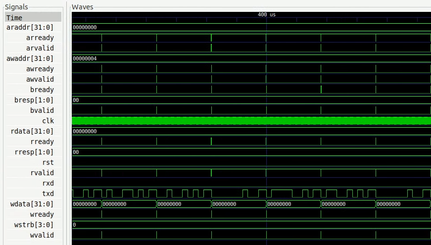
The resulting trace is written into a vcd or fst file depending on the specified option and can be viewed in, e.g. GTKWave viewer.
Core-v-mcu “Hello World” example with verilated UART
Prepare the binary
Instructions on how to set up the SDK are available on the pulp-builder repository.
After configuration, set the PULPRT_HOME environment variable with a path to the pulp-rules directory.
You also need to edit the SDK source code.
To write a character to the txd UART register, add in __rt_putc_uart function in io.c file:
*((volatile uint32_t*)(0x50000004)) = c;
The “Hello World” code source can be found at pulp-rt-examples. To compile, run:
make all io=uart
The resulting binary should be created in the pulp-rt-examples/hello/build/arnold/test directory.
Run in Renode simulation
To enable a verilated UART peripheral in the core-v-mcu hello world example, you need to register CoSimulatedUART in core-v-mcu.repl, e.g.:
verilated_uart: CoSimulated.CoSimulatedUART @ sysbus <0x50000000, +0x100>
   frequency: 100000000
Then, you have to provide a binary to the Renode simulation in the Renode monitor type:
(monitor) using sysbus
(monitor) mach create
(machine-0) machine LoadPlatformDescription @platforms/cpus/core-v-mcu.repl
Attach your binary to the simulation:
(machine-0) sysbus LoadELF @path_to_your_binary
You can use your verilated UART model:
(machine-0) verilated_uart SimulationFilePath @path_to_verilated_uart_model
Or you can use the prebuilt one provided by us:
(machine-0) $uart?=@https://dl.antmicro.com/projects/renode/verilator--uartlite_trace_off-s_252704-c703fe4dec057a9cbc391a0a750fe9f5777d8a74
(machine-0) verilated_uart SimulationFilePath $uart
To enable the UART analyzer window and start simulation, type:
(machine-0) showAnalyzer verilated_uart
(machine-0) s